Monday, April 23, 2007

Ray Tracing - Project 10

Design Choices

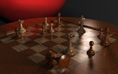
I decided to model a chess set for my image. All pieces in the scene are modeled with triangles except the board (a box) and the ominous red sphere. All the chess pieces were modeled using Blender by myself and exported to the OBJ format, for which I wrote a mesh parser.

The board is rendered using two different Perlin noises and rendered with soft shadows by displacing the light position using a spherical distribution and many samples per pixel. The chess pieces have the same two materials as the board, so I tried to place them on opposing colors so the Perlin noise wouldn't match up perfectly.

This project took me a long time (close to twenty hours, I imagine), mostly because I took so long trying to decide what scene I wanted. I decided to do a chess theme since it gave me a lot of control over how I wanted to lay it out, and I didn't want to do anything too terribly abstract (like a bunch of dragons staring at a heightfield). The final images took around 30 minutes to render using 25 samples per pixel.

Extra Credit

My second Monte Carlo effect was embossed reflections. This was added to materials using a Russian roulette method, where either the diffuse color or the reflected color would be calculated based on the ratio assigned between the two. The embossed reflections were generated by perturbing the normal over a uniform disk. The disk size determined the amount of blurriness.

I originally blended the two colors together, but that introduced a number of artifacts. Switching to the Russian roulette method, these dropped significantly, but I still see an occasional blue splotch. Also, the Russian roulette method looks horrible at low-sampling rates since every other pixel might have a different shading calculation.

This is my final rendered scene using soft shadows and embossed reflections. It took about forty minutes to run using 25 samples per pixel

Code:tracer.tar.bz2

Wednesday, April 11, 2007

Ray Tracing - Project 9

Design Choices

To implement instancing, I created an instance class inherited from the Primitive class. This allowed a simple abstraction for adding groups and other objects and stuff. The preprocess function called the grid layout preprocess for every instance so I added a check to only preprocess once. I used a matrix and a vector to hold the translations and rotations and created to functions for rotating and translating.

This is a really stupid picture of the Stanford bunny rotated and translated around in a strange manner showing the transformations possible with the new instance class


I was feeling patriotic and made a giant bunny flag and just gave it three different colors based on a series of modulos. I was really bored


Code: project9.tar.bz2'

Wednesday, March 28, 2007

Ray Tracing - Project 8

Design Choices

Most of the code modifications occurred in the Scene class. I chose to do this since it seemed logical that different scenes be rendered using different filters and samplings. Also, the Scene class is where the rays are created, so it was a simple change in code.

The code changes had two parts. One which allowed additional samples to be calculated at different points based on the filter, and another part of the code, which calculated the weight of each sampling. I chose the Gaussian filter to implement as it seemed simple and provide okay results, although not too much better then the actual triangle filter.

Rendered with 1 sample per pixel (no jittering)

The function provided in the homework assignment


A scene of random spheres and five different material types


Rendered with 9 samples per pixel with jittering and using the triangle filter

The function provided in the homework assignment


Rendered with 9 samples per pixel using a Gaussian filter


The function provided in the homework assignment


A scene of random spheres and five different material types


Code: project8.tar.bz2

Friday, March 16, 2007

Ray Tracing - Project 7

Design Choices

For the design of the texture mappers, I followed a scheme similar to the one Dr. Parker recommended. I created a TexCoordMapper that provided a basic interface for grabbing texture coordinates. The base object class--from which all primitives are descended--were given a default coordinate mapper, which could be changed through the API.

Besides the coordinate mappers, three new materials were created--a checker material(which used two sub-materials assigned to it), a marble material, which used Perlin noise, and a image material. All three materials were implemented exactly as described in the slides.

Required Image


Creative Image - Triceratops by Rainbow (and sphere)


Extra Credit

For extra credit, I chose to add an additional procedural texture (I'm shooting for half extra-credit). This material (shown in the creative image) allows spectrums of color to be display for effects like rainbows.

Code:http://www.cs.utah.edu/~jstratto/project7.tar.bz2

Wednesday, March 07, 2007

Ray Tracing - Project 6

Design Choices

I originally intended to do a BVH using an quad-tree, where the tree were recurse down to some arbitrary size. This gave me a strange bug (which I had to use for my original image). The algorithm itself seemed simple, but and for the small part of the bunny that it did render, it rendered rather quickly. Much faster than the 2.5 hour attempt without the acceleration structure.

I then tried a uniform grid, but had difficulty debugging it (I wasn't getting anything to the screen), mostly due the short amount of time I had left on the assignment.

I also tried a octree, which gave me similar results to the quad-tree, which makes me feel the bug lies somewhere in my bounding boxes or something.

Bugged Image-If you look really, really closely you can see the form of the bunny. From the part that rendered, it seemed to work effectively, but for everything else, it completely ignored it. It was probably something really small and I probably should have just debugged the quad-tree instead of attempting the other two


Required Image-Here's my final rendering. It took about 18 seconds, wihich was a lot faster than the 2.5 hour version.


Code:project6.tar.bz2

Saturday, February 24, 2007

Ray Tracing - Project 5

Design Choices

The three new material models were a dielectric, a phong, and a metal. All three shared specular properties so code was shared somewhat between them. All materials extended from a general material class which made used of extensive virtual functions to minimize the code base.

Required Image


Code:project5.tar

Tuesday, February 06, 2007

Ray Tracing - Project 3

Design Choices

This assignment added implementation of several primitives including the box, disk, ring, and triangle. The Moller intersection was used to intersect the triangles, as it was the easiest to implement. Amy Miller's implementation was used to implement the box intersection. The new primitives were rendered using existing shaders and the normals were obvious to compute.

This is the default scene for Project 3 using the updated rendering


Creative Image

This scene uses two lights: a directional light and a point light. It features 200 triangles, 60 spheres in a double-helix, a box, and a plane


About this project

Time Required: 5 hours
Difficulty: Easy. Mostly just implementing intersection algorithms
Code: project3.tar

Thursday, February 01, 2007

Ray Tracing - Project 2

Design Choices

Building on the previous assignment, the renderer adds Lambertian shading and two-sided lighting. The material also casts shadow rays through the image, to give a simulated shadow effect. A base object class holds basic properties for subclasses to implement, which include a sphere and a plane. Another base class is for a material, which gives some basic functionality for coloring depending on the vector.

This is the default scene for Project 2 using the updated rendering


This is the same scene rendered from underneath the default plane. Although it appears bleak, it demonstrates lighting and shadows are correctly ignored and only ambient light is applied


Creative Image

This image was rendered using 1000 point lights to simulate soft shadows. It took over two hours to finish and shows the linear scaling of adding point lights to the scene


Extra Credit 1 - Directional Lights

This image was created using only a directional light instead of two point lights. Directional lights render slightly faster than directional lights since they do not have to compute the light vector (it's saved in the directional light object), and no distances have to calculated


About this project

Time Required: ~10 hours (very approximate)
Difficulty: Easy. Lots of typing and organizing
Code: project2.tar

Wednesday, January 24, 2007

Ray Tracing - Project 1

This is the first project for Dr. Parker's Ray Tracing class.

Design Choices

I chose to do a progressive rendering breaking the image up into frames and sending the frames off to separate threads. I chose random tiles, because I felt they would give a better visualization of how the overall scene is rendering. I also liked the idea of using threads as I hope it will get me a bit of a performance boost later. I wanted a rendering style similar to Modo's renderer. I chose C++ because my last ray tracer was in Java (pictures in previous blogs) and was decently fast, but I wanted to do some fast C++.

This is my viewer as it is being rendered kind of how Modo renders (but not as pretty)


This is my completed image. I noticed on the assignment after I was done coding, that I didn't need to handle the depth of the objects


About this project

Time Required: ~15 hours (but I rewrote it many, many times... once for my laptop having the code on it and being in the shop, another for file corruption, etc...)
Difficulty: Not too bad. Lots of debugging since I wrote most of it without testing it, but I'm hoping later projects will be more incremental
Code: project1.tar